This is just a quick photo dump of my CNC router project. I grabbed all the highlights from my facebook page. As I have time, I’ll update this project a bit more. As of 11/15/17, the project is about 97% completed.

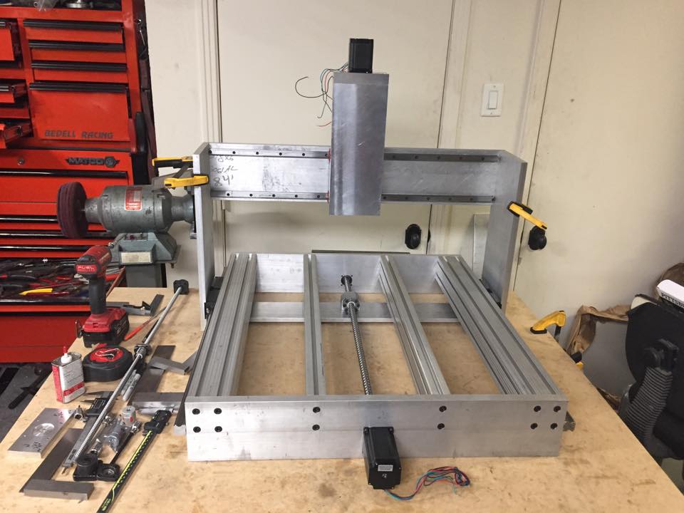
I needed a mental break while the router was carving out the rear panel. Started picking at the CNC router I’m building. Mounted the linear rails on some 1/2 x 2″ aluminum.

Rear ballscrew bearing mount is bored. Just need to drill/tap the mounting holes for it.
Note, I also added two more holes on each side. I’ll be replacing the side rails with a 3×3 piece of 8020. I wanted Misumi milled for this material, but decided that can wait. I’d have to replace both front and rear bars also as I’ve already drilled it for 1.5″ centers, vs 40mm centers.

I was initially going to run the cross bar on top, but I decided to run it on the bottom instead. Dropped the gantry down 35mm. This also facilitated my ability to better build a bed and strengthen the base considerably.
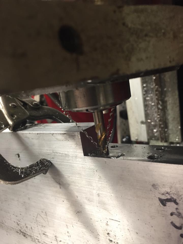
Power tapping. This was fun. I’ve never successfully done this. It took me a bit of time to get the ‘feel’ right on the tension for the collet. I didn’t want it to break the tap if it got in a bind, so I snuck up on how tight it needed to be. Noteworthy here, I set each pair of item in the same setup to ensure they are as identical as possible.
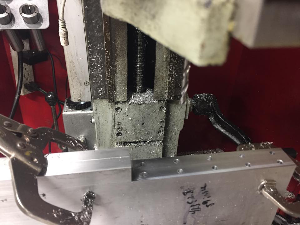
More gantry uprights. Cutting the relief and drilling the holes for the Y axis back plate. Looking at this photo, I remembered that I really need to get a cover back over the Z axis screw.
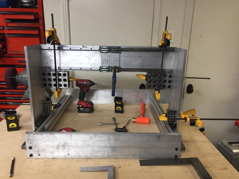
Bolting everything up. So far, it’s square. I have to mount the Y axis rails and ballscrews.
Unfortunately, I measured wrong. Not too bad, but enough that I’m going to have to build an adapter to chuck the ballscrew in the lathe and shorten it about 30mm.
Cleaning up the 8020 ends to ensure they are square and equal lengths.

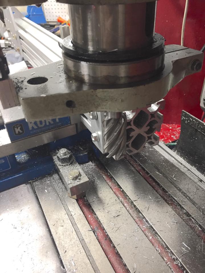
Setting up to cut the Z ballscrew mount. More indexing. I found this repeatable to about .0002. With a ground wire running from the bit to the vise, I probably could have improved it.

Oops. A bit too tight on Z. Easy fix. These three pieces are slated to be replaced in the future. They aren’t quite as ridgid as I had hoped. I’ll do it with aid of the CNC mill once I get it online.

Currently 7.5″ travel with this setup. But I’m scrapping part of it. I need 9″ of travel to get the bit as high as the gantry. I doubt I’ll use more than 5″, but having the option is nice.
Its starting to look like a thing! ballscrew and motor is mounted. Need to get the fixed bearing mounted. Nearly 9″ of overall travel. Only 7.5 or so will be useable.
The back plate on the X axis isn’t mounted yet. I’ll probably get that done tonight. Since I redesigned the gantry uprights a bit, the fitment is less than perfect. I’ll probably eventually replace this piece after I have some precision grinding done on new material.

It was about 2am when I took this photo. I went to bed defeated that night. Wasn’t sure what happened. The next two will tell it.

To shorten it, I had Indexed the new material and ran through everything again. Found my error. I had centered the hole on the material and not from the top.
 Before I cut again, I wanted to make sure it looked about right before I started drilling a new mount hole. When finished, the new one was dead on. no misalignment at all. The top piece is the mistake and the bit is where it should have been. Cut twice, measure once right?

Ballscrew Block is almost finished. Need to measure and calculate its best position. Then drill/tap holes to mount it. I don’t like the seal clearance. It’s silly tight. I’ll see if I can find some sealed bearings that will work here. In the end, I will just do wipers, I wasn’t able to get this assembly all sealed up.

Working on the control box. Couple more hours left from this point.
Gecko G540 is the main control at the top: Gecko G540
I’ll list out the DIN rails, 48v power supply, circuit breaker and DIn 12v Power supply in another post or later.

Water pump mounted. This is it on amazon: Water Pump
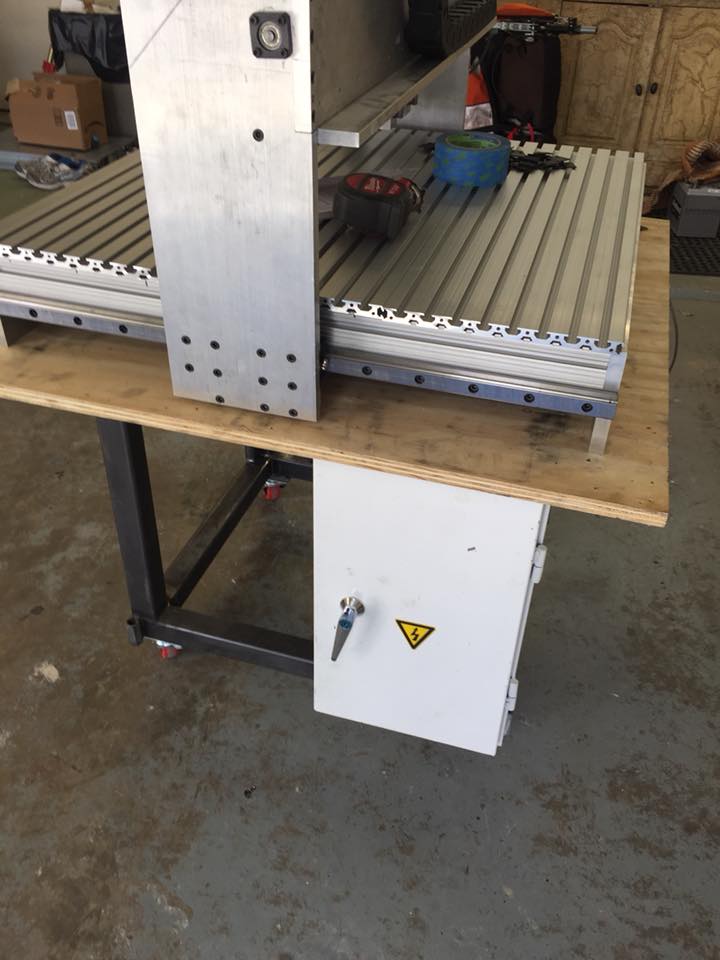
Control box is mounted. Unfortunately, the latch had to go. I’ll have to figure something else out.
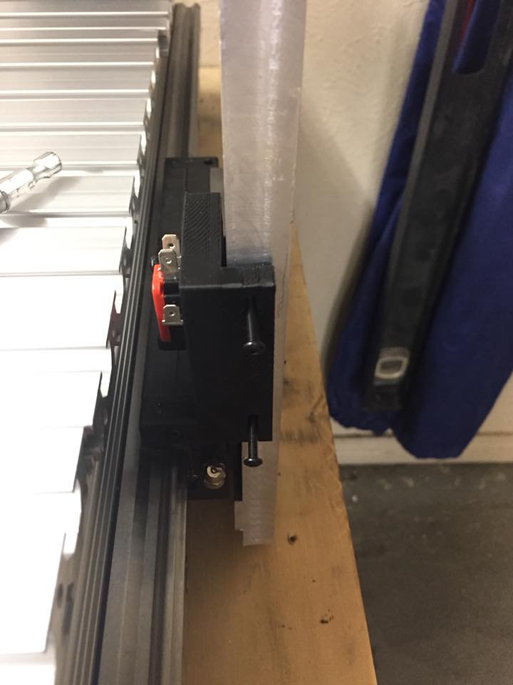
Y axis home switch. The 3d printer was useful for this.

No Limits!

Pretty happy with this. Need to do a little cleanup, but wanted wires a bit long for troubleshooting or moving stuff a little.

These were more trouble than they were worth.

Spindle at 24,000rpm. About 3’ away. Should be really nice with an enclosure around it.

Keyboard and monitor tray. Need to buy a drawer for the computer.

You can tell the age on this keyboard/monitor. It’s really blue!

Side view. Coolant pump filled up. Seems to work well. I may need to add a radiator to it in the future. Will wait and see.
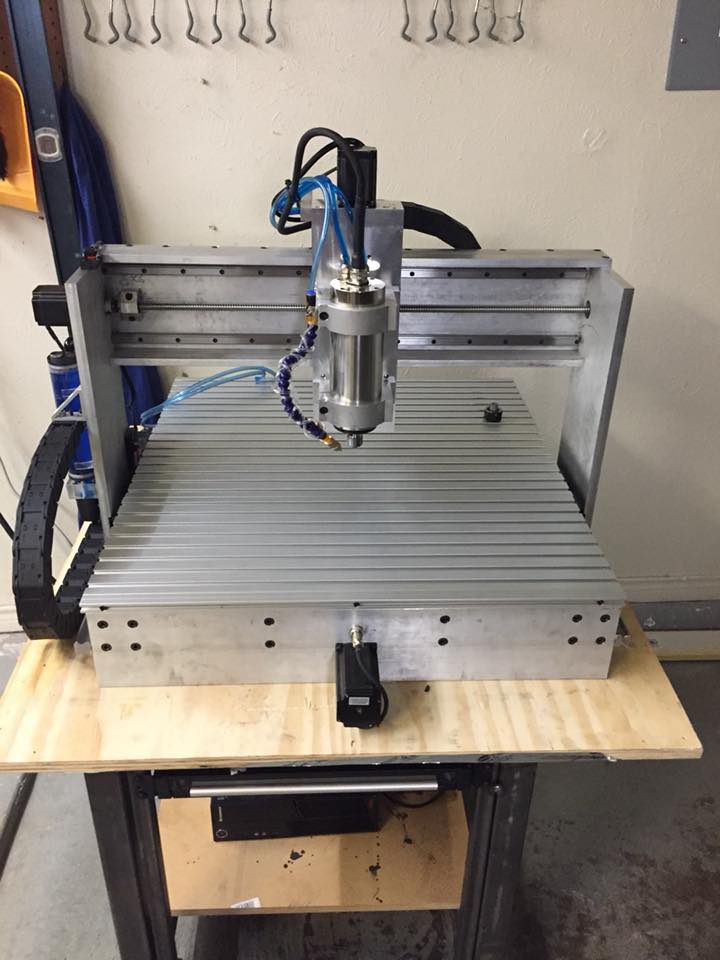
Front of the Router. I Still need to install a few cable ties here.
I had this all drawn out and planned, but changed it before I was completed. had to order more Misumi extrusion to optimize the plexiglass. I’ll take a better photo of it in the future.
Update 24 March 2018
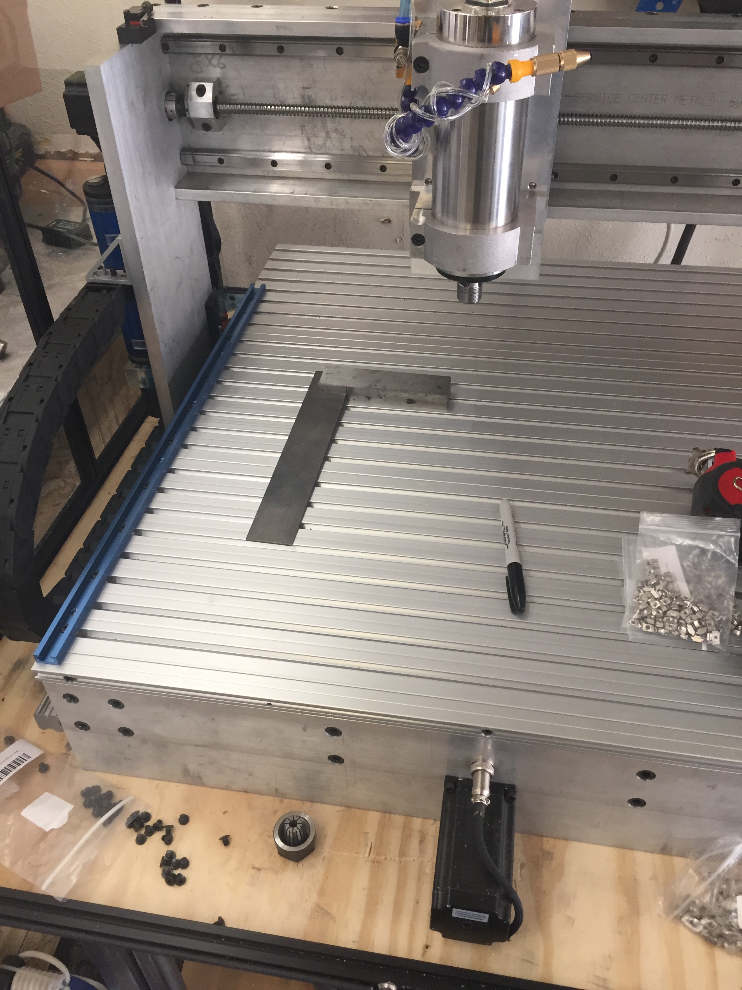
I finally got around to doing the spoilboard. I ended up with 8 pieces of 24″ t-track from amazon. It’s 3/8″ thick and takes 1/4″ and 5/18″ t-bolts.

6 are kinda fitted. I ran out of bolts, so I ended up quitting. Back to amazon for more hardware. Next time, I’ll count my bolts on hand.
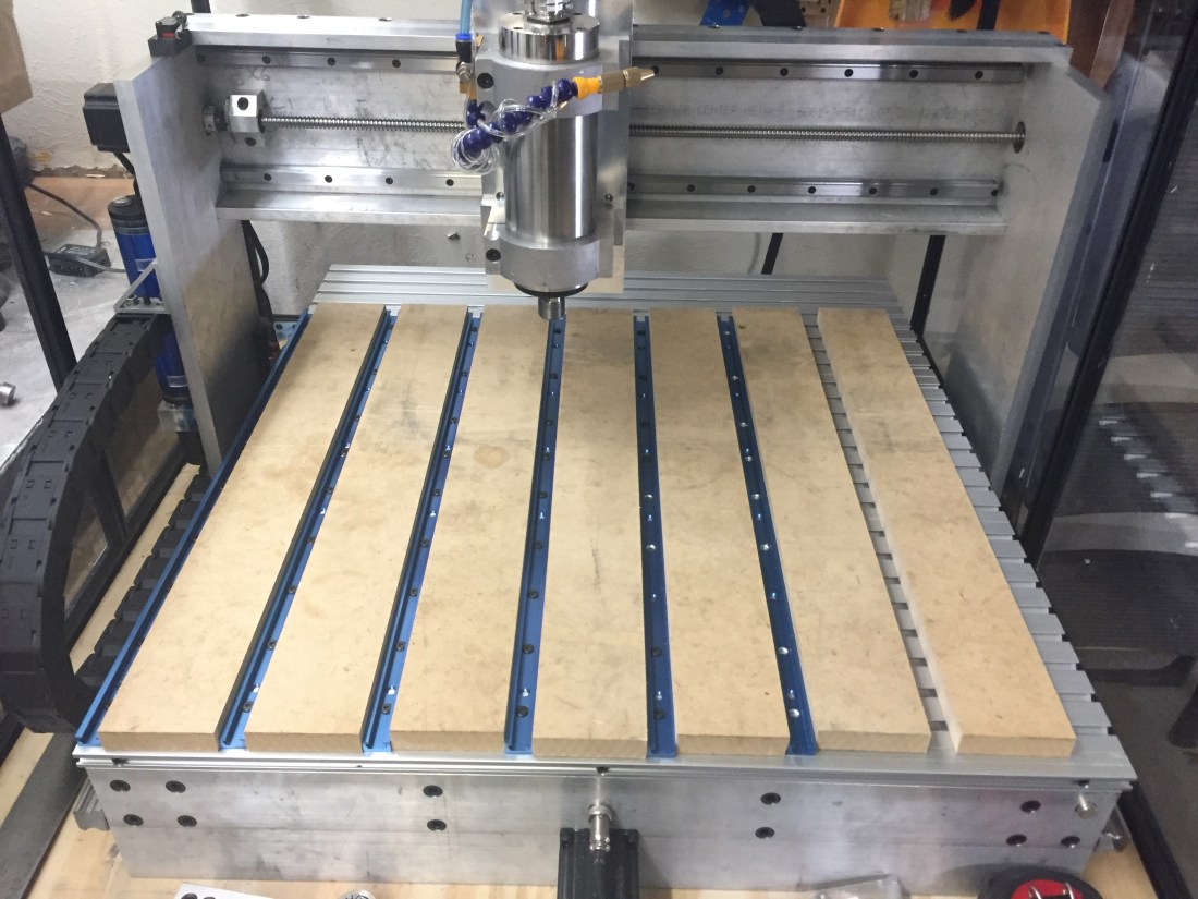
I still need to drill the holes for the MDF. For starters, I’ll use 6 bolts, but I may end up with 10 to reduce any vibrations. I’ll eventually switch to hardwood or maybe even some sort of plastic if I can get a decent deal. But for now, this should be pretty decent. My garage is climate controlled when I’m working in it and pretty well sealed up when I’m not. I shouldn’t see much difference in the MDF size once I surface it. Although, I’m going to look at potentially sealing it somehow, I’m just not sure I can penetrate the MDF enough to then surface it and it remain sealed.
With this wave of work, I’ll be adding in an aquarium pump for chip blowing. Initially, the manifold will be pretty straight forward and just Tee off the current block. Future will be a blower/shoe combo for chip blowing and recovery.
3 March 2019
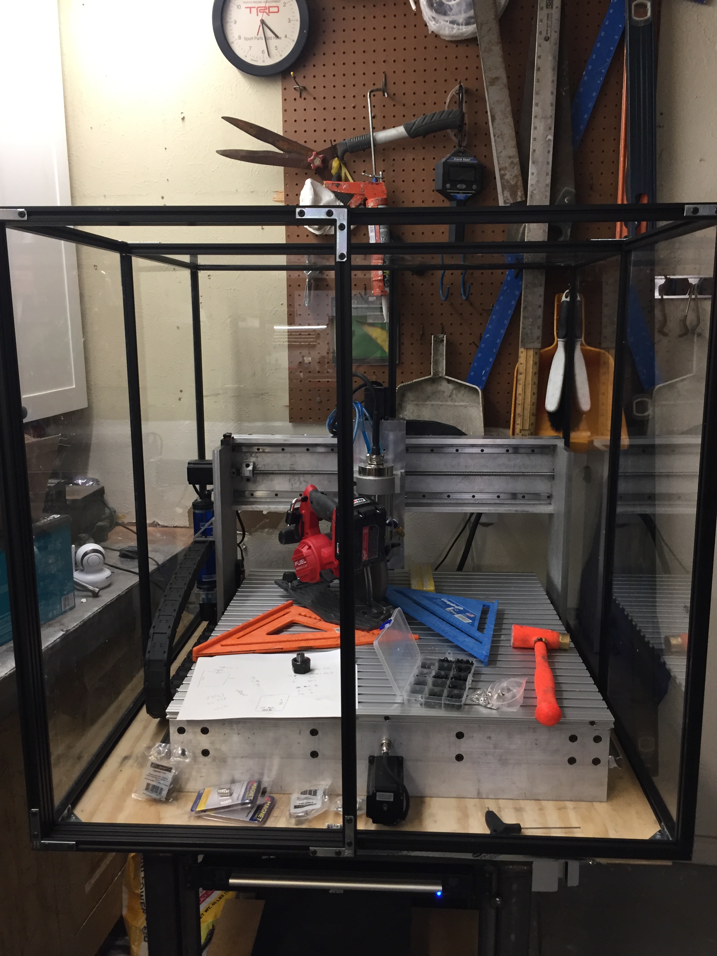
It’s been a while since I’ve updated this, life keeps happening. I’ve done a few updates to this router, specifically the spoil board, coolant-proofing the enclosure and Z axis have seen significant improvements. The photo below is the updated enclosure and spoilboard.
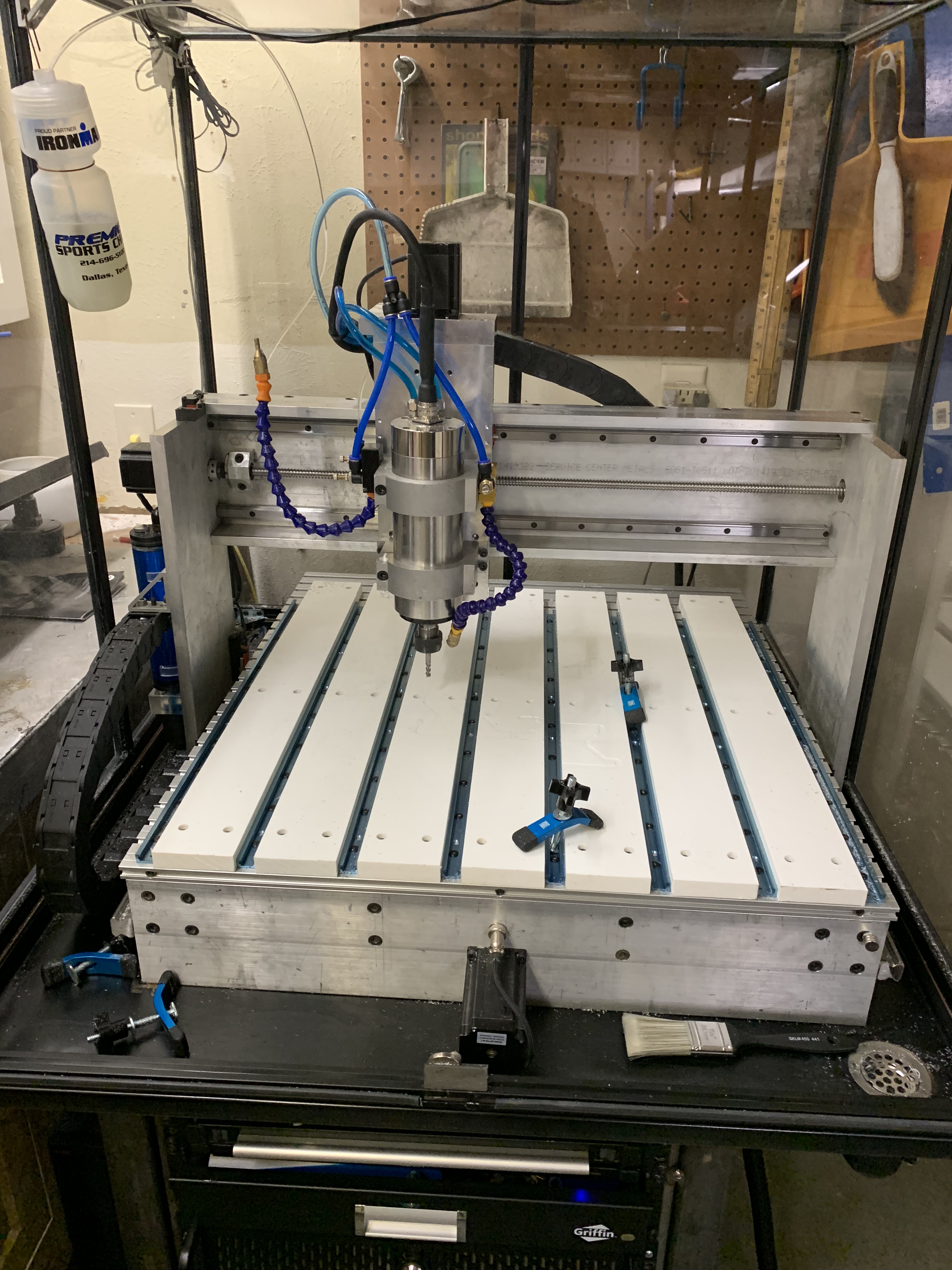
Below is the new spindle mount. I’ve not finished up the switches on the Z axis, but with the soft limits in Mach3, I’m finding i generally don’t use them.

